
MOSAIC ENGINEERING ARCHIVE
Historical / DiscontinuedMFT Camera Filter Installation
Recovered installation procedure for the Mosaic VAF/IR-BMD-MFT optical filter and precision shim kit.
IMPORTANT
Micro Cinema Camera + Speed Booster
The recovered instructions require the shim kit when this filter is used with a Blackmagic Micro Cinema Camera and a Speed Booster.
For the other listed cameras, installation of the shim kit was optional but strongly recommended to correct the filter-induced back-focus shift.
BEFORE YOU BEGIN
Kit Components & Tools
Install the shim components before inserting the optical filter. Work in a clean, well-lit area and keep tools and loose hardware away from the sensor glass.
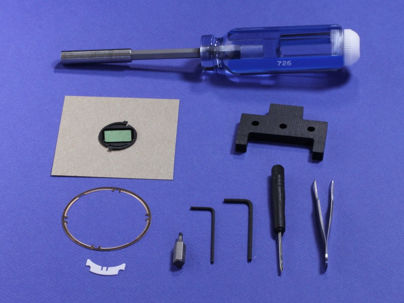
Supplied Tapered Driver
Used for the MFT flange screws.
1.5 mm Hex Key
Used for the electrical contact block.
Small Phillips Driver
Used for the retaining assembly.
Fine Tweezers
Used for the shims and optical filter.
TOOL NOTE
Use the supplied tapered driver on the flange screws.The original screws are soft and may contain thread-locking compound. Seat the driver firmly and squarely before turning.
PHASE 01
Remove the MFT Flange
Open the mount carefully and keep the original parts together.
Loosen the Four Flange Screws
Seat the supplied tapered driver firmly in each screw. Keep it vertical and loosen all four flange screws.

Lift the Flange
Remove the four screws. Hold the lens-release button down while lifting the flange, then remove the original stainless spring shim and the small black plastic part.

PHASE 02
Install the Contact-Block Shim
Create the required clearance, insert the white shim, and return the contact block to a secure position.
Loosen the Phillips Screw
Beneath the removed black plastic part is a small Phillips-head screw. Loosen it approximately two to three turns.

Loosen the Contact-Block Screws
Using the 1.5 mm hex key, loosen the two black socket-head screws about four to five turns—only enough to free the electrical contact block.

Move the Contact Block Forward
Use tweezers to pull the electrical contact block gently forward. Move it only far enough to create space for the white shim.

Insert the White Shim
Hold the shim by its two slots with tweezers and slide it beneath the contact block.
It should seat fully and remain completely outside the optical path.

Secure and Inspect the Block
Gently retighten the two socket-head screws, then the Phillips screw.
Confirm the block is straight, even, and slightly forward of its original position.

Reinstall the Black Plastic Part
Return the small black plastic component to its original position. Confirm it sits flat and does not interfere with the contact block or lens-locking mechanism.

PHASE 03
Install the Optical Shim & Reassemble
Build the shim stack flat and return the MFT flange to its alignment pins.
Position the Bronze Optical Shim
Place the machined bronze circular shim against the camera body with its recessed inner perimeter facing away from the camera body.

Replace the Stainless Spring Shim
Set the camera's original stainless spring shim on top of the bronze shim.
It must sit fully and flush inside the bronze shim's inner recess. Their front faces should form one clean, flat plane.

Replace the MFT Flange
Set the flange onto its alignment pins and against the flat shim stack.
It should settle naturally into position. Hold it in place, release the lens-release button, and reinstall the four screws.

Tighten the Flange Evenly
Bring the four screws down progressively, a little at a time, while watching the entire perimeter.
Keep the flange flat against the shim stack.

PHASE 04
Install the Filter & Verify Clearance
Center the optical filter, then use the supplied gauge before mounting a Speed Booster.
Seat and Center the Optical Filter
Snap the filter gently into place in front of the camera's blue-green sensor glass.
Use tweezers to center and straighten it over the sensor.

Check Filter Clearance
For a Speed Booster installation, rest the appropriate side of the supplied gauge flat against the metal MFT flange.
The gauge should not touch the filter.

Check the Speed Booster
Place the opposite side of the gauge against the Speed Booster.
It should rest flat on the flange face while leaving a small gap to the rear-projecting optical-cell snout.

FINAL INSPECTION
Check the Installation Before Mounting a Lens
Verify the mechanical assembly and optical area before completing the installation.
- MFT flange is flat and evenly secured
- Optical filter is centered over the sensor
- White shim remains outside the light path
- No debris, fingerprints, loose parts, or tool marks remain
- Speed Booster clearance has been verified with the gauge, if applicable
RELATED HISTORICAL INFORMATION
Continue From the Installation Procedure
Return to the product overview, review technical guidance, or browse the broader Mosaic archive.
Blackmagic Camera Filters
Historical overview of Mosaic VAF and VAF/IR products for selected Blackmagic camera systems.
Back to Product Family →Technical Q&A
Background on optical anti-aliasing, focus, polarization, camera integration, and historical VAF operation.
Explore Technical Q&A →Legacy Products
Browse the broader Mosaic Engineering archive of historical imaging systems and optical products.
Browse Legacy Products →LOOKING FOR CURRENT OPTICAL PRODUCTS?
Continue With Mosaic Optoelectronics
This page is retained as part of the Mosaic Engineering historical archive. Current optical anti-aliasing, polarization, crystal-optics, and custom optical inquiries are handled by Mosaic Optoelectronics.